
Composite propeller manufacture for performance model aircraft.
This article aims to describe in simple terms the techniques that I have used for the last 30 years to manufacture composite propellers for high performance model aircraft.
The more open minded modellers who read the article may also see that the techniques described could also be applied to other components that are essentially manufactured in closed moulds rather than an open layup.
If the article is read and understood then most people will get reasonable results at the first attempt, I managed this over 30 years ago!!
Why use composite propellers?
As the performance of model aircraft increased during the 1960’s due to a number of significant new engine performance enhancements such as Schnuerle porting and tuned pipe exhaust systems, then the demands on the only item that actually drives the model forwards became ever stronger, hence the need to look at the materials used in the manufacture of propellers.
Wooden propellers had been the material of choice since the start of IC powered models as far as competition flying was concerned, with the plastic injection moulded commercial offerings of the 1950’s and 60’s just not being up to the job of handling high output engines.
Composite material development was moving at quite a pace by the end of the 1960’s with the first commercial use of carbon fibre occurring in the Ford GT40 and glass fibre reinforced plastic becoming common place. Innovative modellers of the time realised that these materials would make a superior replacement for wooden propellers. By the early 1970’s people like Jim McCaan in England and Jurgen Bartels in Germany had moved the production of composite propellers to a commercial level to the benefit of many modellers.
Jim McCaan published an article in Aeromodeller in the early 1970’s that outlined the requirements for producing tooling to manufacture composite propellers and the actual manufacture of the propellers from those tools. When I started manufacturing my own propellers for F3D pylon racing in 1983, I referred to the Jim McCaan article and my early propellers were exactly as defined in those articles.
Of course time moves on and I have refined the tooling and production process over the last 3 decades to produce a much higher specification propeller than the early 1980’s examples, although these advances are more biased towards material improvements as opposed to the basic techniques involved. In this article I will explain the tooling and production requirements I have learned over the years.
Firstly what is a composite propeller?
Composite materials in the context of this article means a combination of two or more materials. This combination will give enhanced material properties over either material if those materials properties were taken in isolation. There are two distinct families of composite propellers used in model flying these are.
Injection moulded, fibre filled thermoset plastic. I have been careful not to say glass filled nylon here, as there are now a number of other filling fibres apart from glass, it also must be said that the nylon element in these propellers may be substituted by other types of material suitable for injection moulding. There are a multitude of manufacturers of this type of propeller, popular types are APC, Graupner, Radio Active etc. etc. we are not going to look into the construction of these type of props in this article as these items are largely a ‘buy and fit’ product, and production in a home workshop is not possible.
Resin, filled with continuous fibres. This is the type of propeller that we will be looking at in this article. These prop’s are standard fitments in most competition control line classes, a number of free flight competition events and radio control events such as pylon racing, F5B and aerobatic events where a high performance propeller is desirable.
The materials used in a composite propeller will be a resin, either polyester or epoxy, although in recent years this has become almost exclusively epoxy resin and of course the fibres. The fibre content can be made up of either glass fibre, carbon fibre or mixes of the two, again in recent years this selection of fibre has largely come down to carbon fibre. So we can see that the composite of these two materials makes a material with great properties for a high performance model aircraft propeller.
Composite propellers of this type can be made in the average modellers workshop without any expensive machinery, using materials which are fairly easy to obtain.
Tooling
The actual propeller mould tool can be produced by two distinct techniques, these are moulding a tool off of a pattern propeller or manufacturing a metal tool by CNC machining techniques. Whilst the CNC technique produces marginally better tooling it is out of the scope of most ‘Fred shed modellers’, so we will only cover the moulded tooling technique in this article.
With the moulded tooling technique, the first thing that is required is an existing propeller to make a copy of. This propeller could be an original carved pattern or more likely a propeller that has evolved through experience and use during competitive flying. At this point I would like to point out that should you be planning to make a direct copy of an existing unmodified propeller then you should seek permission from the originator of that product as they by default have intellectual copyright over it’s design and form.
There are some hardware items and materials that are required to manufacture the propeller mould tool and these are as follows. Supplier details can be found at the end of the article.
-
2 off steel plate, bright drawn bar 50mm x 6mm section or similar, length to be 30mm more than the prop diameter.
-
1 off centre post, this can be aluminium or steel, length to be 30-40mm more than prop depth.
-
Formica sheet, or any smooth sheet material, enough to make a perimeter wall as described later.
-
Release wax.
-
Plasticine.
-
Tooling material, this can be plastic padding but it is better to use a metal filled epoxy.
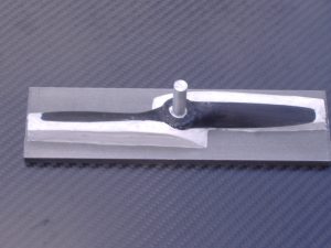
Firstly we must manufacture a centre post that the prop sits upon during manufacture of the tool and subsequent component manufacture. Normally this centre post is a piece of metal bar that is the same diameter as the hole through the centre of the prop, in some cases the pin maybe of a stepped type, this means it will have two diameters with the larger dia representing the hole in the back face of the prop hub see pic. 1).
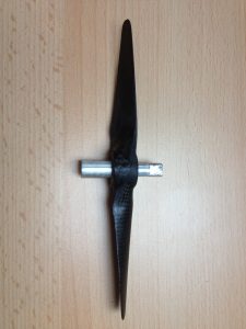
The centre post can be manufactured from the shank of a drill in an emergency if it is of the non stepped type. Flats are machined/filed onto the upper end of the post to assist in removal.
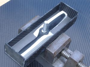
The next stage in making the prop tool is to cut a baseplate, at later stages this also serves as a backing plate for the tool to enable high clamping pressures to be used. The base plate should be cut to a length 30mm longer than the diameter of the prop being copied. A hole should be drilled in the centre of the base plate to take the centre post see pic. 2).
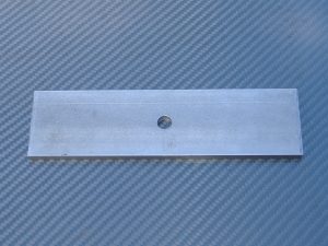
This hole should ideally be drilled in a vertical drill press to ensure that it is perpendicular to the base plate and is sized to enable a snug fit for the centre post, do not try to achieve an interference fit, as this will cause troubles in the de moulding stages.
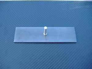
Apply release wax to the top surface of the baseplate, the centre post and the pattern propeller. I have not found it necessary to polish these items to a shine, in fact there is a lot of comfort to be had in leaving these surfaces slightly wax rich to ensure an easy release.
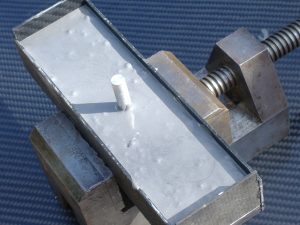
Assemble the centre post into the baseplate see pic. 3)
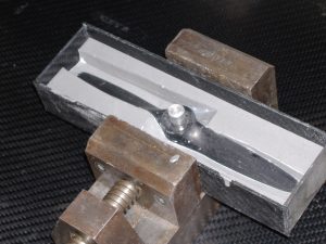
Then push the prop over the centre post see pic. 4).
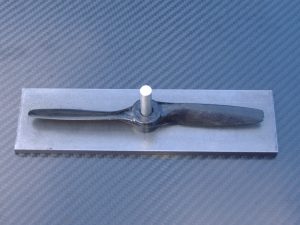
Now using plasticine pack out under the prop to create the split line for the tool, the LE and TE’s make a natural split line, when you arrive at the hub either try to follow the existing split line or create a new one, however you must not create an undercut which will trap the pattern prop in the tool with disastrous consequences, see pic. 5).
Next we must build a ‘bund’ wall around the base plate to retain the liquid tooling material until it cures. This ‘bund’ wall can be made of any flat sheet material that the tooling resin will not stick to. The simplest material for this could be plywood wrapped in plastic parcel tape to provide the release, alternatively Formica or cured composite sheets could be used to achieve the same result. What ever material is used ensure that there are no gaps in the joints, otherwise the tooling material will leak out before it has cured, forming cyanoacrylate fillets on the ‘bund’ wall joints will help provide a leak free construction. The bund wall must not be higher than the centre post, proportions for the height of the bind wall can be gauged from pic. 6).
If the ‘bund ‘ wall is not of a self releasing type material then a release wax must be applied to the internal faces.
Now we are ready to pour the first half of the prop mould tool, a basic volume calculation would pay benefits at this stage to ensure that not too much material is mixed causing waste. The preferred material to use at this stage of the process is a preprepared metal filled epoxy, Jim McCann recommended Plastic Padding, whilst this can be used if an epoxy material is not available, I would not recommend it because of higher shrinkage rates on cure due its polyester resin composition. There is a possibility that an adhesive material like JB weld might be good for prop tooling material as it is tough and can resist reasonable temperatures, although at the time of writing this has not actually been tested.
Mix your chosen tooling material according to the manufacturers instructions, observe all H&S recommendations from the material supplier. If the material is not of a paste type allow it to stand for a short period of time to allow trapped air to rise, this of course assumes that you are not using a fast curing material which would exotherm. Pour the mixed tooling material into the ‘bund’ wall see pic. 7)
If the mixed material in the pot has a lot of air bubbles at the surface then use a blade held across the pouring edge of the container to only allow a restricted amount of material through and to hold back the frothy surface, it is very undesirable to introduce air into the mould tool at this stage. Allow the tooling material to cure making allowances for reduced workshop temperatures causing extended curing times.
Once the tool has cured break off the bund wall. Now carefully prise the mould tool away from the baseplate, this will also require gentle pushing of the centre post from the underside of the baseplate. Once the mould is broken away from the baseplate, you will have to clear out the plasticine from the under side of the propeller and mould, initially this can be done using a plastic scraper (an old prop is also good for this) however do not scrape into the corners too hard. I have found that for final removal of stubborn plasticine in the corners that release wax applied with a cloth will melt the plasticine, this also helps ensure that the mould tool is treated with release wax for separation from its opposite half.
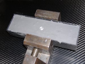
Apply release wax to the sides of the tool, the tool face, the underside of the propeller and the centre post, now build the bund wall around the tool again, see pic. 8).
Once these operations are complete, then pour the second half of the mould tool, do not cover the centre post with the poured material for clarification of this see pic. 9).
Once the second half of the mould tool is cured then drive the centre post out of the two mould halves and prop pattern, remember to observe the direction if the post is stepped, I usually use a press for this operation as I feel using a drift and hammer would be too harsh on the mould tool at this stage. Before splitting the two mould halves, scribe some alignment marks across the split lines to ensure correct mould assembly/orientation in the future.
Now split the mould halves apart, against my better judgement I always have to start the splitting with a Stanley knife, once the split has started then an old propeller is very good for wedging the mould halves apart. Once the mould halves are apart it will be possible to remove the propeller, which will be attached to one mould halve, again the tip of an old propeller blade pushed underneath the pattern propeller will enable the pattern to be pried off the mould tool.
Now the backing plates need to be attached to the mould halves, clean up any bubbles that are causing an irregular surface on the back sides of the moulds. Generally I find that it is best to use a flexible sealant for this bonding operation, a silicone sealent will be fine. This flexible seal is essential if the propeller mould tool is to be used with heat during curing due to the different thermal expansion figures for the mould tool and backing plates.
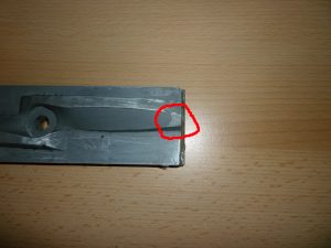
Final finishing of the mould tool will involve removing any flash lines at the edges of the mould and at the point where the plasticine meet the pattern propeller. A small amount of filing is required on each tip of the bottom mould halve, to allow excess fibres to exit the tip see pic. 10).
The mould tool is now complete and ready for the first propellers to be produced from it.
Making the propeller
Firstly we must prepare the mould for production and collect the required tools and equipment together, following is a list of these items and the supplier details are at the end of the article.
-
Release wax.
-
Carbon fibre cloth and carbon fibre tows.
-
Epoxy resin.
-
Digital scales.
-
Mixing pots.
-
Disposable gloves.
-
Brushes and acetone.
-
Scissors and knives.
-
‘G’ clamps 3 off.
Apply release agent to all surfaces of the mould tool and the centre post, I would recommend at least 5 applications of the release wax prior to the first moulding operation being carried out, generally follow the release wax manufacturers application instructions, however I usually leave the last application of wax in a slightly wax rich condition to promote easier release of the component.
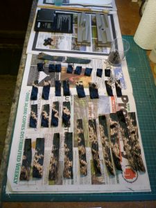
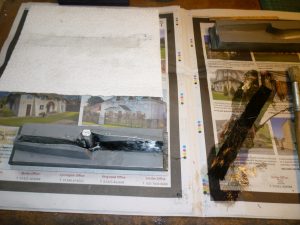
A clear work surface is essential, although it does not need to be very big, my whole work area for the production of propellers is the size of an unfolded newspaper (see pic. 1)
Basic requirements for a good propeller moulding
Before commencement of moulding we must understand some basic factors that go to making a good composite propeller.
The most important thing to remember is that you are making a safety critical item, a propeller blade breaking up at high RPM could be very dangerous. Having said this in over 30 years of competition flying I have not seen a dangerous occurrence with a composite propeller of the type described in this article. Follow the guidelines and advice below and you will build a huge safety factor into the propeller.
For most competition model flying propellers we are looking for a stiff and strong propeller, this is obtained by getting the correct ratio of fibres and resin. This may sound a little off putting but the usable fibre to resin ratio is actually quite wide and the old modellers adage of ‘ if it looks right then it probably is right ‘ will stand us in good stead.
If the resin ratio is too high we will end up with a flexible propeller that is not very strong, conversely if the fibre content is too high we will have a propeller that is very stiff but liable to de-laminate. The high resin content is much more likely to be the error with propellers produced by the novice constructor.
I like to arrange for long tip to tip fibres to be on the back face of the propeller and gradually decrease the fibre length from this, this achieves two things the first being that it makes the prop very resistant to bending forwards and secondly it ties the two blade halves together nicely. I then decrease the length of the fibre bundles towards the hub and then finishing with a set of long fibres at the front face of the blade.
I do like to to use a fine carbon fibre cloth, something in the region of 80 to 120 grams per sq/M on the front/top surface of the blade, this is laid with the fibres at 45 degrees to the span of the blade. This cloth serves two functions, firstly it helps in the blades torsional stiffness i.e. resistance to de-pitching and secondly it helps stops the blade splitting from the tip towards the hub in minor contact with the ground. This material is not essential.
Determining the fibre bundle size for your propeller
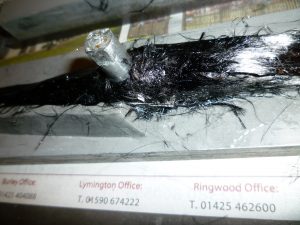
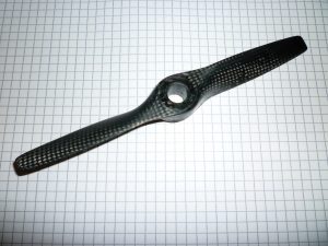
Regrettably I know of no ‘magic formula’ for determining the fibre bundle size that goes into a composite propeller short of knowing the closed volume of the propeller, so this means that this material determination is largely through an empirical knowledge, you can see in the photo’s the amount of material that goes into a 170mm diameter F3D pylon racing propeller, this will give a good idea of how the fibre bundle builds up during the layup of the propeller.
Cut the carbon tows that you have chosen to use and lay out neatly to enable them to be easily picked up with gloved fingers. Always ensure that there are two fibre bundles for each length of fibre, in this way you are able to place fibres on either side of the centre pin. (see Pic1 for an idea of the fibres ready to layup).
At this stage also cut some fibres into small lengths of around 2mm, these are used as filler fibres. The chopped fibres can be seen in the photo’s contained in a plastic cup.
Starting the actual layup of the propeller
Mix your chosen resin system, observe all H&S recommendations from the material supplier. For a propeller such as the type featured in this article which is 170mm diameter you will need less than 25 grams of the mixed system, gauge your requirements from this information. If you have to mix more resin it is not a total disaster but just a little inconvenient.
I always layup the bottom half of the mould first and work up through the blade. Firstly brush a small amount of mixed resin over the mould face for the lower blade half. Using the chopped carbon fibre strands fill any sharp corners in the hub area of the mould tool (see Pic. 2)
Now proceed to wet out the first piece of long fibre, I always wet the carbon on a sheet of newspaper (see Pic. 3)
Now gently push the resin through the fibres, if you think that the fibres look excessively wet then you can use a piece of paper kitchen towel as a blotter, this towel can be seen at the top of the picture mentioned above.
Always ensure that the fibre bundles are split into two (mentioned earlier) and straddle the centre pin.
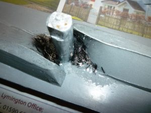
Gradually work through the fibre set, I find that after the 3rd fibre bundle has been placed into the mould that a cavity starts to form between the fibres and the centre pin (see Pic. 4)
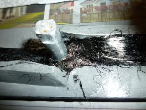
Use the chopped carbon fibres to fill this cavity. Complete the main layup with another set of long fibres going from tip to tip and straddling the centre post (see Pic 5).
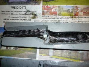
Now move to the top half of the mould tool and brush in a thin coat of resin and apply chopped carbon filler to any sharp corners. Next lay in the fine carbon fibre cloth onto the wet mould surface, carefully force the resin through the fibres with the resin brush (see Pic 6).
Once this operation is complete we are ready to close the mould tool, finally check that everything looks as you expect. Take note of the tool alignment marks, place the bottom mould half on the work bench and push the top half down over the centre pin. With a little weight applied you will practically close the mould tool. However much more clamping pressure is required, I generally drop an old socket over the centre pin to enable a ‘G’ clamp to apply pressure equally around the centre pin (see Pic 7)
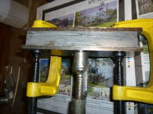
Finish the clamping operation with a ‘G’ clamp applied towards the tip of each end of the mould, apply reasonable pressure to close the mould as shown. If your fibre filling has been excessive you might not get a good closure on the first moulding, if this is the case adjust your fibre filling for the 2nd moulding of the propeller.
Allow the propeller to cure at room temperature for around 24 hours and then de mould the propeller. Splitting the mould apart is just the same as splitting the original mould tool apart, ie take the centre pin out first. Some people heat the mould tools to cure, I prefer a room temperature cure with a free standing post cure of the component after de-moulding.
Post curing and trimming of the propeller
Post curing is a term that describes a further curing and development of a resins mechanical properties. Basically most mouldings unless they have been post cured have an element of uncured resin within the matrix.
Refer to the resin suppliers technical information to determine the post cure requirements, if you are unable to achieve the requirements indicated then at least place the propeller over a domestic radiator or inside the flexible jacket of an immersion heater, don’t be tempted to use a domestic cooking oven if for no other reason than the temperature controls are very crude and you run the risk of over heating and distorting your work.
Now trim the flash/excess material off of the propeller, I use a combination of a Dremel and assorted files for this task, finish off the edges with 240 grade wet and dry paper. Observe all H&S recommendations from the material supplier when carrying out the trimming operations.
Finally balance the propeller, I still prefer the twin wheel type of balancers having found them to be more sensitive than the magnetic balancers where the shaft is pulled up to magnet face. Don’t be surprised if the propeller is some way out of balance, firstly check that your trimming is equal and symmetrical for both blade halves, if the prop is still out of balance then proceed to sand off material from the top side of the heavy blade.
You should now have a usable composite propeller which will be the envy of your flying friends. (see Pic 8)
Supplier listing for mould tool materials
Metal base/backing plates – Metal Supermarket check yellow pages or web.
Ebay traders – Metal Mania
Centre post – Metal Supermarket check yellow pages or web.
Ebay traders – Metal Mania
Hardware shop for drill bits to cut up.
Release wax – R&G composite supplies http://shop1.r-g.de/item/165130
Ebay traders – Composite Supplies UK
Mould tool resin – R&G composite supplies http://shop1.r-g.de/item/115169
Bund wall material Hardware shops that sell Formica laminates.
Plasticine – R&G composite supplies (Germany) check web
Supplier listing for composite propeller materials
Release wax – R&G composite supplies http://shop1.r-g.de/item/165130
Mould resin – R&G composite supplies http://shop1.r-g.de/item/110149
Reinforcement fibres – R&G composite supplies http://shop1.r-g.de/item/205102