
21N The Beginners’ Control Line Speed Class
Welcome to part 2 of our introduction to flying and competing in CL speed events, the response to part 1 has been very encouraging we already have three newcomers committing to taking part in 21N CL speed, and the age range is encouraging as well.
In this part we will look at the engine, associated power train parts and the airframe. Remember 21N is an open event, there are very few rules, what we present here is a way to get going and then to think up and implement your own ideas and improvements, after all that is what CL speed is about.
We would like to consider this introduction as an Open Source project, we will make as many drawings, instructions and information available as possible. So you can make as much or as little of the speed model and power train as you wish. We would encourage you all at this stage to share your ideas, you will find this a much quicker way to reach success and you may well make new friends along the journey as well.
Many potential modellers who may be interested in having a go at control line speed flying are put off by the complexities and the need to have specialist machinery and parts to put a speed model together, however this need not be the case. It is not necessary to have a metal engine pan, metal or carbon fibre wings etc. A competitive model can be made from traditional materials, however, it is very much a personal choice on which way to run with this class
The 21N class was developed specifically for newcomers to control line speed flying and has specific restrictions. It is a BMFA Open Speed class which beginners can take part in up to the point of breaking the current BMFA speed record for that class, after which they are no longer allowed to participate.
The reason for the restrictions is to keep the class as fair as possible for competitors of similar abilities and skills in both flying and model building. In addition to this, the performance is restricted by the use of Super Silencers, Magic Muflers etc and eliminating the use of Tuned Pipe silencers and with all the attendant fuss of setting them up. Models must be flown on 2 lines (no monoline allowed). Fuels and propellers are unlimited.
ENGINES
The biggest issue in speed classes generally is the availability of suitable engines. In bygone years there were several manufacturers of high performance engines such as Super Tigre, Rossi, OPS to name just a few and all produced a useful range of engines, including .21 sized units. Sadly, none of these are manufactured any more, unless we are lucky enough to pick up good second hand motors such as those mentioned above but there is always an issue of maintaining these engines with increasingly sparse availability of spares.
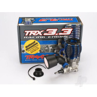
So, in this particular class ( and a couple of others ) there is availablity of brand new motors and a healthy supply of spares, These are engines that are used in R/C cars of .12, .21 and .28 sizes and can be picked up at very reasonable prices. The budget end motors are around £70 and top end motors can cost as much as £350 but there is no need to go as extravagant as this there is every chance that the cheap engines if setup and run correctly stand as good a chance in competition as a £350 engine.. The performance of these cheap engines would appear to be quite satisfactory for our purposes as they are ported and tuned for high revving performance.
We will explain the modifications required to get the engine to a suitable state to run in a CL speed model. Kits for adapting the Force car engines to use in 21N will be made available at reasonable cost. Due to the very generic nature of these car/buggy engines the conversion kits may well fit engines other than the Force series.
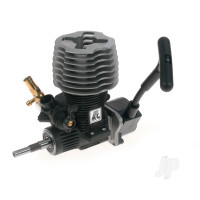
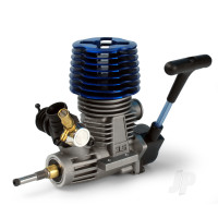
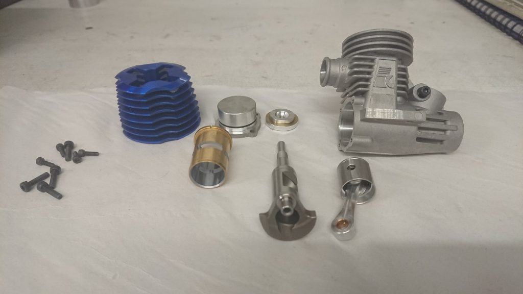
Finning it Down
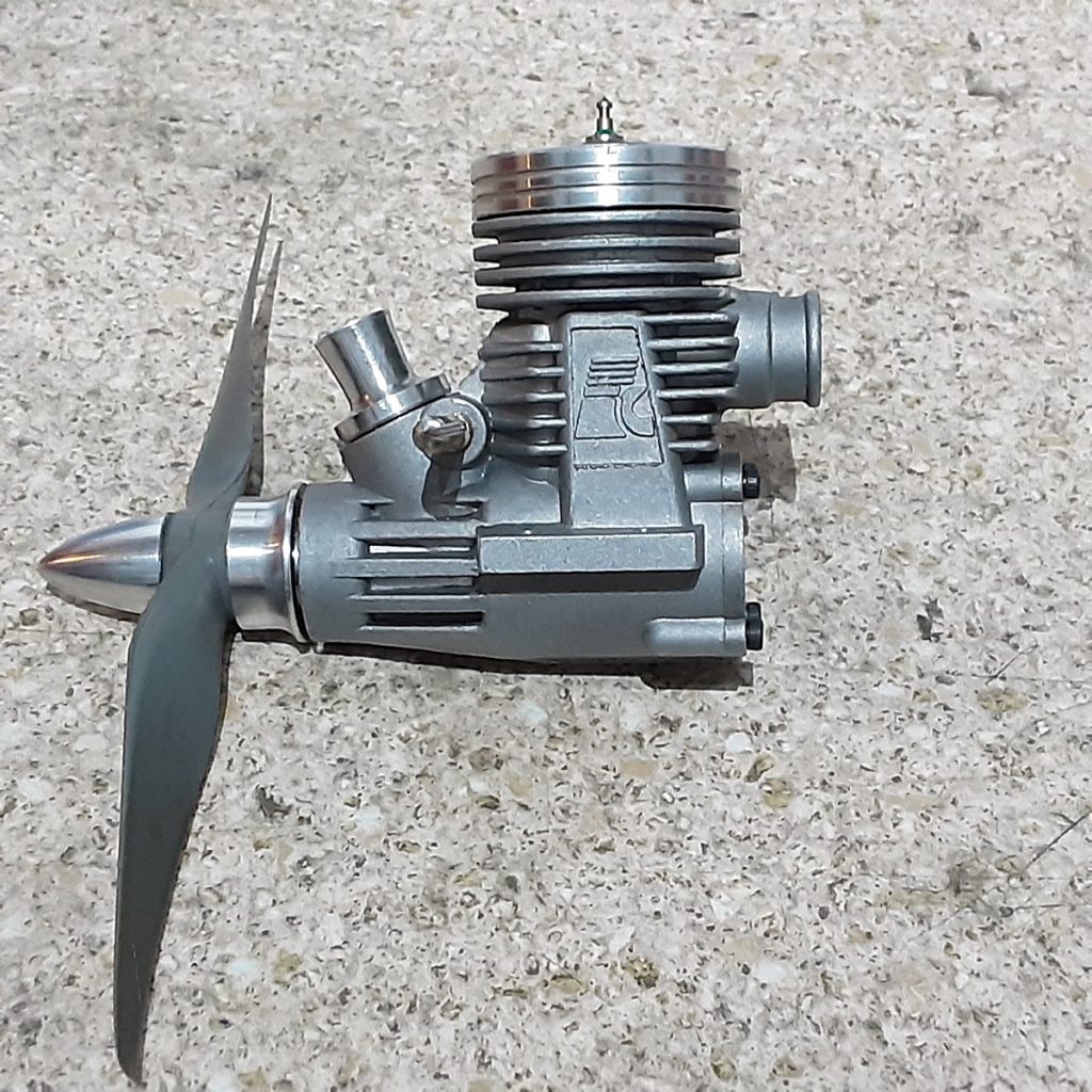
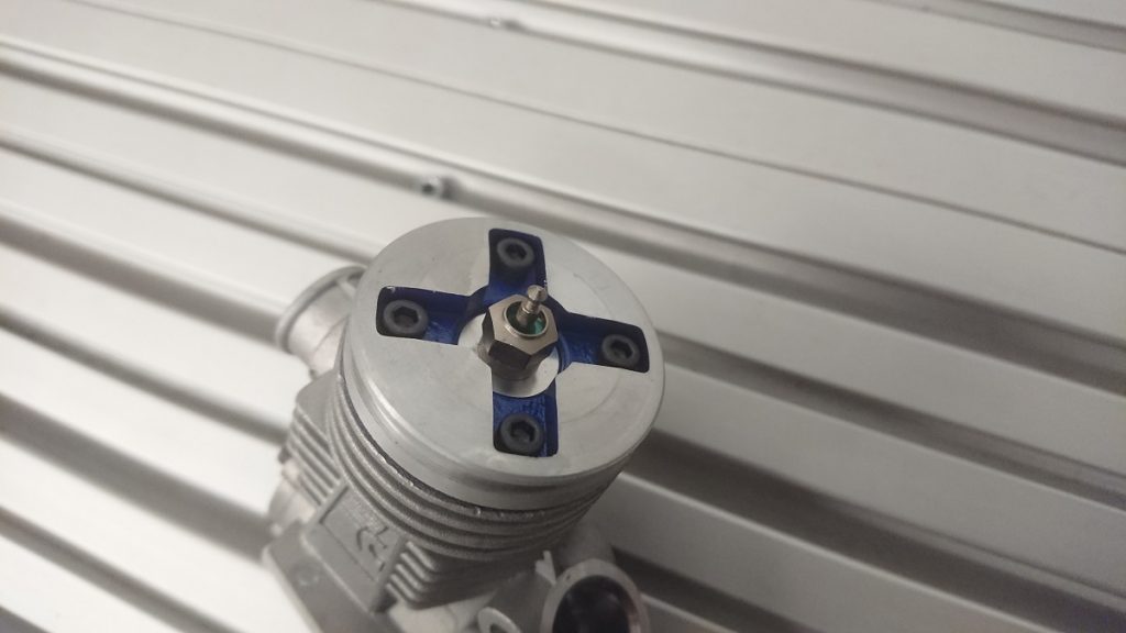
The first thing that jumps out at you is the massive cooling fins which, obviously, we do not want on an aero engine. In the majority of cases the cylinder heads of these engines are made as a 2 part unit being a head button which is inserted onto the cylinder chamber and forms the combustion enclosure of the engine. The head button is clamped into place by the cooling fin jacket. This arrangement enables the engine to be converted to aero with ease and does not necessarily require the use of a lathe. The jacket can be put in a vice and the fins carefully removed with a hacksaw and the face and edges finished up with a file and abrasive paper. Alternatively, if you are fortunate enough to have access to a lathe then you could machine a new head clamp for the engine. The photo below shows an engine with newly machined head clamp.
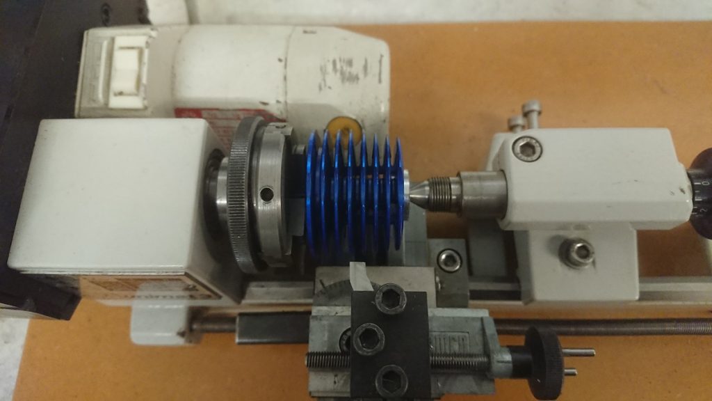
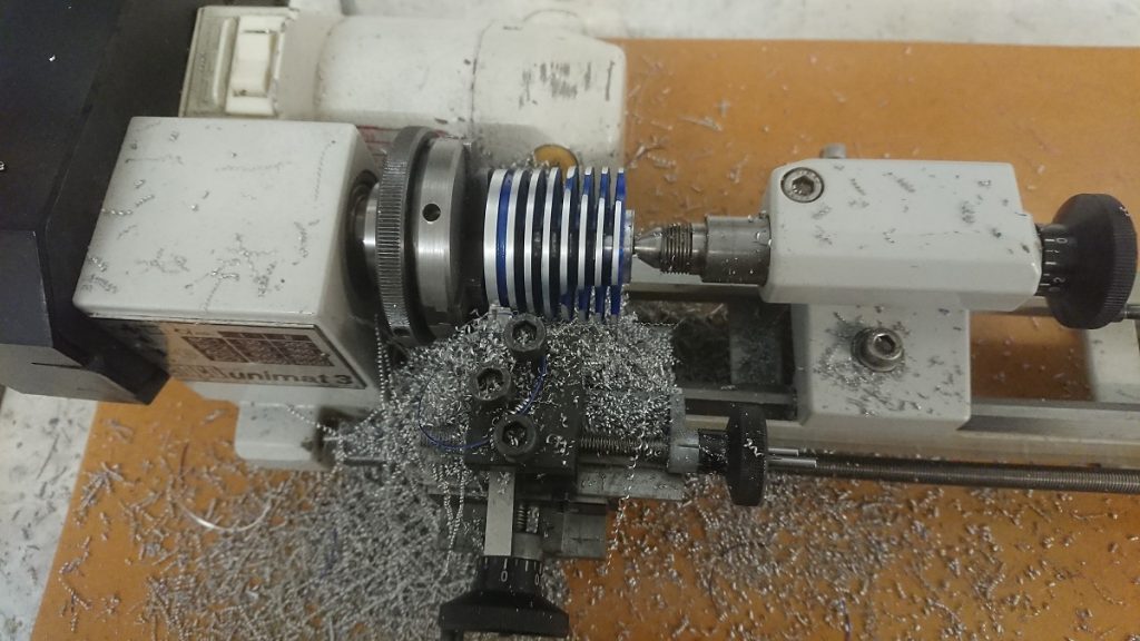
The photo’s below show the standard buggy cylinder head being modified easily in a very small Unimat 3 hobby lathe. The head is held on the internal diameter that fits over the head button insert and a temporary bung supports the head from the tailstock, once the buggy head is turned down to the correct diameter the top 7 fins are hack sawed off out of the lathe. Parting off would be unwise as there is not a lot of head engaged on the chuck jaws. Finally face it off and put a chamfer on the edge.
This is certainly not pretty and will not win any beauty contests but it shows how easily 21N engine mods can be carried out at very low cost.
Choking up
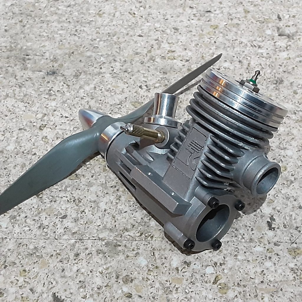
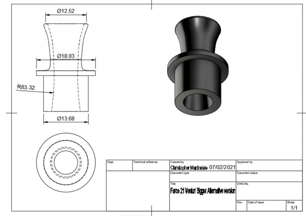
The R/C carburettor is a clamp in unit which can be removed and discarded or sold on e-bay. A venturi could be fabricated from plastics such as delrin (acetyl) or aluminium using hand tools and a drill press. Easier to do on a lathe but not impossible. A commercial spraybar and needle valve of suitable diameter can be substituted into the pinch bolt hole for the R/C carb. This will provide securing for the new venturi. Alternatively a venturi could be purchased from Just Engines which may fit or might need minor modification with hand tools
The image below shows how a typical home manufactured venturi such as the one shown on the complete engine would look in cross section.
The Pullout
The pull starter can be removed and a traditional backplate purchased and installed. Some manufacturers (such as Force) supply a standard backplate as a spare part, the cost of this with O-rings and mounting screws is £4.99. A lot of model engine crank cases are generic so a backplate from one make may fit another. As a last resort a commercial backplate could be machined to fit or a bespoke unit fabricated.
Prop It Up
Some car engines come with a conventional propeller driver but the majority do not. However, the manufacturers may make a prop driver as a spare part (such as Force £3.99) or again. alternatively, a propeller driver from another make of engine may fit and as a last resort a prop driver could be machined if you have access to a lathe.
The current 21N record was set using a £2.60 APC 7×6 prop but within the normal rules (no metal) then the prop is a free development area.
Going Nuts
There is one area of a R/C car engine that will present some problem and that is the crankshaft output. Invariably these engines are manufactured with what is termed a SG crankshaft which is not threaded all the way to the front. They are made this way in order to carry a flywheel and clutch assembly. This is not such a large problem and is simply resolved by the use of a bespoke sleeve nut to retain the propeller. These can be obtained from speed flyers who have machining facilities, or if you have a friendly machine shop they could make one for you but they are not unobtainable.
Magic Muffler
The rules for 21N speed do not allow the use of full wave tuned pipes but rather a “Magic Muffler.
Magic Mufflers are actually a tuned silencer of half wave magnitude and are quite simple, in principle, to construct. If one considers a trombone with it’s sliding valve to tune the tone, then this is not dissimilar to how a magic muffler is tuned.
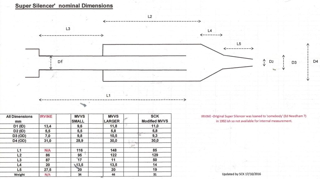
The photo below shows a table of dimensions for the fabrication of a Super Silencer and we would suggest the MVVS Large Dimensions dimensions would probably suit our .21 ships There will be an element of trial and error between pipe length and propeller dimensions to achieve the desired results.
The silencers can be built from thin walled 6082 T6 tube, however there will need to be some lathe work done to make the end cap and tail stinger/outlet but the basics are there. The front endcap could be made with a collar and ‘O’ ring fitted that grips the header, this would then allow the outer pipe to be “tromboned” to tune the pipe/engine/ propeller set up and then fixed at the optimum performance. The silencer components can be assembled with JB Weld or Slow Setting Araldite with some aluminium filings in the mix.
There will be Super Silencers available for purchase should a competitor not wish to fabricate their own device.
LET’s BUILD A MODEL
The model choice is entirely up to the individual as to whether to go with a traditional wing and tail layout with upright engine, or asymmetric with upright or sidewinder engine.
The whole ethos of this project is to eliminate the amount of hard to get parts such as engine pans etc, down to a minimum.
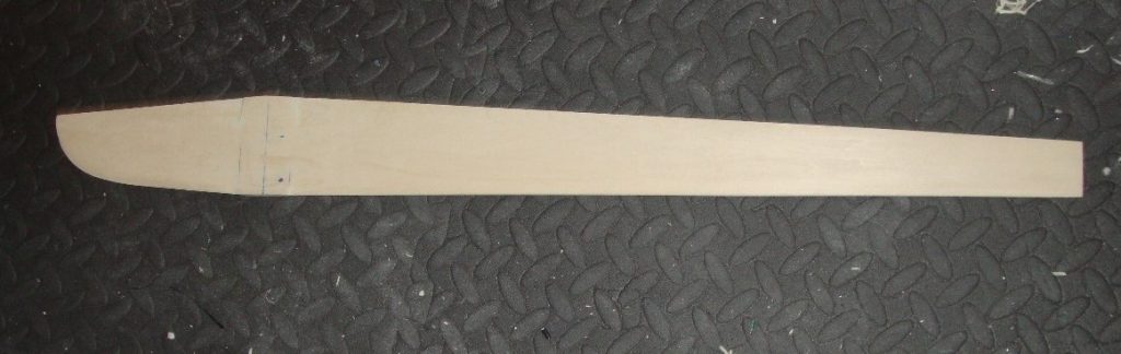
Fuselage / engine crutch can be made from 12mm Basswood ( or 2x 6mm laminations ) fitted with alloy plates for engine mounting and the cowling / fuselage top carved from laminated basswood/balsa and a basswood / balsa or plywood tailplane
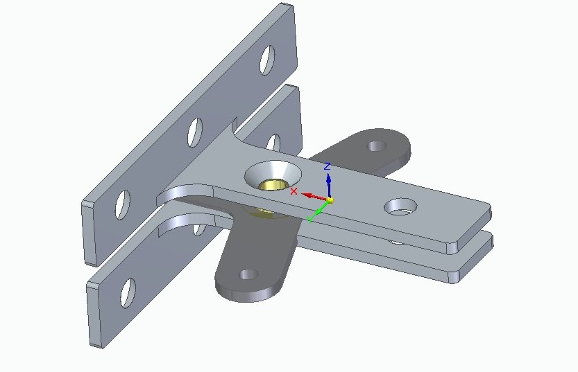
An asymmetric form sidewinder model such as the outlined design below would have to utilise a folded aluminium wing to keep the inboard side light. This does present some complexities in the construction in respect to bellcrank / stub spar mounting in a wooden fuselage. Also, pushrod routing could be problematic. All not insurmountable but just needs a bit of thought and the solutions could be as simple as a fabricated bracket / bellcrank mount fixed from the outboard side of the fuselage Basswood crutch as depicted below.
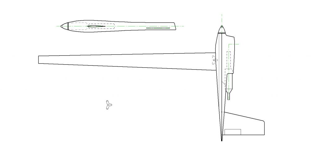
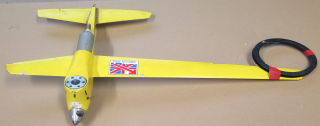
However, an upright engined semi-asymmetric would work well with a wing made from balsa / basswood as per the yellow model pictured below. The latter would make for a simpler build and still be competitive.
The timber work of the airframe can be finished with sealer/primer and spray painted or lacquered clear, however, a glass / resin finish would be beneficial in that it will impart strength and stiffness into the airframe. So, there is scope for utilising traditional materials up to using more exotic materials.
The model design for which we will provide plans and kit parts for will be the yellow semi-asymmetric design featured above. Materials like Basswood are available from SLEC and they also still have hard balsa wood in stock so no excuse to not start building.
Part 3 will detail the model build and have plans for the above model and a full materials and hardware listing.